CTC Definitions for z Systems
I don't mean to offend my IBM brethren, but the Channel-to-Channel (CTC) documentation in the IOCP book is abysmal. Don't get me wrong; all the information you need is there, but it's kind of spread out. If your configuration is exactly like the examples, you're all set. Otherwise you have a lot more homework to do.
What I intend to do here is to blow away the fog and the seeming illogic of the I/O definitions for FICON CTCs. Rather than hand you a fish, I want to teach you how to fish. I want you to be able to configure CTCs for any environment, not just the ones in the books!

To begin, I need to turn back the clock and talk about the basic tenets of CTCs back in the days of S/360 and S/370. The CTC protocol hasn't changed much since then, but the implementation has changed a lot!
Conceptually, a CTC adapter (CTCA) is a double-sided control unit that pairs together the unit addresses on opposite sides of the adapter. In this picture, the unit addresses are numbered 0, 1, 2, and 3.
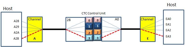
In this example A28 is paired with EA0, A29 with EA1, A2A with EA2, and A2B with EA3.
Refresher: Back in those days, the device number referenced by the host was the real device address: CUU (channel, unit, unit). The UU was was 0-n, plus the control unit address. So unit address 5 on control unit C0 attached to channel 3 would be referenced as 3C5. Different control units had different rules for what was a valid CU address.
Later, the standalone single channel-pair CTCA was replaced by the IBM 3088 Multichannel Control Unit.
This control unit contained (wait for it....) multiple CTCAs that could interconnect the channels on an any-to-any basis.
The low-order two digits of the device address determined which remote system you were talking to, as predefined by the IBM 3088.

The above ia logical representation. Physically, everyone connected to the IBM 3088:
     RUBY                                         SAPPHIRE
   .--------------------.       CUADDR= -.       .--------------------.
   |    To        Use   |         ______ V       |   Use       To     |
   | SAPPHIRE : 800-803 |        |      |C0      | 2C0-2C3  : RUBY    |
   |                    |===== 00| 3088 |========|                    |
   | EMERALD  : 804-807 |        |______|        | 2C8-2CB  : EMERALD |
   |                    |          || 20         |                    |
   '____________________'          ||            '____________________'
                                   ||
                                   ||
                                   ||             EMERALD
                                   ||            .--------------------.
                                   ||            |   Use       To     |
                                   ||            | 724-727 : RUBY     |
                                   ::============|                    |
                                                 | 728-72B : SAPPHIRE |
                                                 |                    |
                                                 '____________________'
While there was a method to the numbering madness, few understood it. But we didn't have to since the 3088 manual contained a nice chart with all the relationships described. All you had to do was plug in some numbers, et voilà! Perhaps you remember filling out one of these and taping it to the side or cover of the 3088? I know I do!
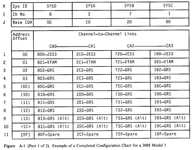
Of course, as a VM guy, my chart was filled with things like VTAM, TSAF, PVM, and RSCS.
But once ESCON arrived on the scene, the 3088 faded into history. Both ESCON and FICON emulate the CTCA internally. With ESCON, you had to choose which side was the channel and which was the CTCA, but with FICON, you don't have to worry about that. The adapter makes intelligent decisions about which side should have which role.
Let's talk about FICON devices and how they are addressed. Consider that a FICON channel can communicate with thousands of devices. To communicate, every device needs to have a unique address so that the FICON frames are sent to the proper device.
On the host side we still have our trusty device number, but it's really just an indirect reference to a channel path, a control unit that can be reached by that path, and a specific device managed by that control unit. When the channel subsystem sees inbound data from a particular device unit, the channel subsystem can figure out which host device number will receive an interrupt and get the data. This information is all established via IOCP or HCD.
To wit:

That's kind of obvious, right? Right. But now I'm going to complicate things: Add a second LPAR. Well. Hmmm. See the problem? We need a way to differentiate A00 on LPAR 1 from A00 from LPAR 2.
Rather than complicating the device numbering scheme, IBM engineers decided to update the low-level channel protocols to include additional information that lets the channel subsystem manage I/O from multiple LPARs on the same channel. To go with that they invented the Multiple Image Facility (MIF). This is a function of the channel subsystem that adds the specific information needed on outbound frames to let the receiving system respond to the correct partition.
When you think about an IBM Z I/O configuration, consider:
- The physical I/O configuration with all of the I/O adapters, their phsycial channel IDs (PCHID numbers), and cables.
- The logical I/O configurations, or Channel Subsystems (CSSes), to which each partition is assigned. It's here that we find CHPID numbers, CUs, and devices. It's also here that we find access lists that control which LPARs can see which CHPIDs, CUs, or devices.
- The channel image. This is the I/O configuration as viewed from inside a single parition. Access rights have been applied. Every LPAR has its own channel image.
To identifiy a specific channel image, we must know both the CSS and the Multiple Image Facility (MIF) ID of the partition within that CSS. The channel image ID uniquely identifies a partition in a machine.
The channel image ID is a two-digit hex value, where the first digit is the logical channel subsystem (CSS) ID to which the LPAR belongs, and the second digit is the LPAR's MIF image ID in that CSS. Both of those values are obtained from the LPAR's definition in the I/O configuration.
For example, given that I have three systems; RUBY, SAPPHIRE, and EMERALD:
     RESOURCE PART=( ( CSS(0),(RUBY,1),(SAPPHIRE,2) ) ,
                     ( CSS(5),(EMERALD,B)           )    )
We know that RUBY has channel image ID 01, SAPPHIRE has 02, and EMERALD has 5B.

The area of the FICON frame that contains the channel image ID was previously zero. Consequently, a MIF image ID of zero means that the CPC is running in Basic Mode and there's only one I/O configuration using the channel subsystem. And that, boys and girls, is why you can't assign an LPAR a MIF image ID of 0!
A thousand words:

The use of the channel image ID enables the channel subsystem to differentiate the I/Os performed by different LPARs using the same device number. The control unit and device don't care. They just return data to the channel image that requested it.
The arrival of ESCON on the scene signaled the end of physical CTC CUs. They were replaced by firmware running inside the channels themselves. One end of the connection played the role of the channel and the other end played the role of the CU.
That's all well and good, but it creates a bit of a CU addressing problem. How are you supposed to address a seemingly non-existent CU? As it turns out, by the channel image ID I described above. So if RUBY wants to talk to EMERALD, the channel image that RUBY is using must have a CU that references the channel image that EMERALD belongs to. Likewise, EMERALD must have a CU that references RUBY's channel image. It won't work without BOTH definitions.
Let's look at that in more detail.
You can see the three of our four LPARs, Ruby, Sapphire, and Emerald.


Each LPAR is using a point-to-point (PTP) FICON connection to talk to the other LPARs. This is required even if you want an LPAR to talk to itself!
The channel image ID move back and forth on a CTC, there must be some kind of addressing information in the layer 2 CTC frames sent on the FICON channel. Sure enough, each frame includes an origin channel subsystem (CSS), control unit (CU) and unit address (UA), as well as a a target CSS, CU, and UA. They perform the same function as MAC addresses in an ethernet network.
In fact, a switched FICON connection is essentially a non-broadcast multi-access fabric (a WAN), and a PTP FICON connection is like a LAN. But in either case, they require that frames contain origin and target communications endpoint addresses.
This means that Sapphire has information in its IOCDS about Ruby, and Ruby has information about Sapphire.
In particular, Sapphire has to know the CSS and and MIF ID of each of Ruby's LPARs which which any of Sapphire's LPARs will communicate. Bottom line, the sender is able to send because it has a definition for the receiver, and the receiver is able to correlate the incoming data because it has a definition of the sender.
A first glance, this seems very strange, but I guess it only seems that way because I always think of your average FICON control unit as being attached to the local CPC. Well, it isn't. Rather, the FICON chpid is just a gateway to the outside world and the control units have destination addresses to differentiate them from the others connected to the chpid. (LAN semantics, again!)
Which means the only truly odd aspect is that we have a configuration item in the IOCDS that represents the CTC control unit's view of the world. We don't usually see that sort of thing since it's normally handled in the separate control unit software, but the CTC CUs are integrated into the channel subsystem.
Here's the important part: The CU is the MIF ID of the origin and target LPARs.
There is no real CTCA any more, so the CU numbers are at the discretion of the folks who designed
the integrated CTCAs, and they said "CU= Let's start off with the basic assumption that you've managed to physically connect Sapphire's chpid 63 to Ruby's chpid 73
with a single cable.
In order for Sapphire S4 to SEND data on a CTC to Ruby R1, it needs
three pieces of information
In order for LPAR R1 to RECEIVE data from LPAR S4, I need three pieces of information
As the sender, Sapphire needs to put the receiver's MIF ID and a unit address into
the CTC frame before it transmits it down the cable. Sapphire gets information
from the IOCDS. Specifically, it uses the Cn there in the form of
"At the other end of my chpid 63, you will find a paired chpid that has
of this cable (one of Saphhire's chpids),
you will find a CU defined with the MIF ID of one of Ruby's LPARs. You
will queue this data on the device of that CU that has same unit address as the device
address I'm using to send it.
my MIF MIF ID x. The unit address on that
In order to define the CTC, the IOCDSs on both sides must have
information about the other side.
CHPID 60
CU=
CTC connections are created by a low-level
Establish Logical Path operation in which the channel on
one side and the CU on the other exchange information.
The local channel knows about the
chpid on the receiver's CPC, and a unit address to identify
a specific device on the target control unit.
unit address to identify a specific
multiple LPARs.
Each is connected to the other two via two FICON channel paths (cables).
Consider what has to happen when Ruby receives a frame of
data from Topaz on a FICON port. Ruby has to answer
two questions:
The rest of you, keep reading. (This is fascinating stuff, isn't it!
Hello? Hello? Is this thing on?)
Where were we? Oh, right. Who gets the data. Or more
specifically, which of Ruby's devices will receive the
data?
It turns out that Ruby makes the decision, with some hints
provide by Topaz. Just like in the olden days, we
create a CTC by connecting Side A and Side B together with a
cable. You know what? It's still true!
What's also true is that Side A and B are ignorant of each others'
to talk to: LPAR x in CSS y. So a CTC frame is transmitted
very similarly to an ethernet frame. It contains
origin identification, target identification, and the data.
(I'm oversimplifying, of course, but you can live with that.)
To send a CTC frame from R1 to S1, a miracle occurs. No, wait, that's
not right. No miracle. Just some simple logic.
There are
auto-discovery mechanisms that are used, but they're not part of the CTC
protocol, but are in the application itself.
The answer to the first question is simple: The other side included
thme LPAR. How does it do it? The frame itself contains the
information. How did it get there? The other side put it there,
of course.
So, in order to send data, you have to address it to a specific
unit address on a specific control unit in a particular logical
channel subsystem defined to a particular LPAR. Just four simple
pieces of addressing information.
As you likely suspected, every frame also includes that same information about the sender, so that
when the frame arrives at the CPC, the I/O subsystem will locate locate the control unit definitions for the
destination LPAR and will search for the CUADDR that matches the sending LPAR.
In order for two LPARs to talk to each other, each must have a (sub)channel that is talking to
a CTC control unit. Of course, CTC control units don't physically exist any more, so we talk about a
logical CTC control unit image. This CU image is imbedded in the CTC firmware in the z
Systems FICON adapters. Each CU image you create via the CNTRLUNIT UNIT=FCTC statement
is bound to a specific LPAR in a specific channel subsystem. The
CUADD parameter identifies the CSS and MIF id of the target LPAR.
It follows that two LPARs can talk to each other only when there are two CUs define, one bound to each
of the LPARs. FCTC subchannels on each LPAR will be associated with the CU of the peer LPAR, which
may be on the same CPC or a different one.
In this treatise I use the phrase "local LPAR" to mean the LPAR that you are trying to manage.
A "remote LPAR" is one that is trying to talk to the local LPAR. As perspective moves,
don't forget which is local and which is remote.
Hopefully Alan's Rules for FICON (ARF, for short) will help. To wit:
There's no crying in System Programming. As Tom Hanks said in 1992's A League of Their Own,
Leave everything you know about configuring ESCON or parallel channels at home.
They are dead and buried. Requiescat in pace.
CHPIDs on both sides are coded as TYPE=FC. No worries about which end of the connection will play
Channel and which will play Control Unit. It's magic.
A single physical path can communicate with multiple LPARs, whether on the same or different CPCs.
There are two types of configurations:
Switched. Two FICON ports are logically connected to each other through a FICON switch.
A switched connection is only way you can connect two LPARs on the same CPC with a single channel.
And before you ask, no, there is no ability to
Your local LPAR's I/O configuration must have a separate CTC CNTLUNIT definition for
every remote LPAR that it wants to talk to.
(Don't ask questions, yet. Just accept it for now.) That control unit will be associated with the
CHPID you use to reach the destination.
with each CHPID that you will use to communicate with that target LPAR.
(Of course, for high availability you will always have at least two.)
You can put up to 256 CUs on a single FICON chpid, so that shouldn't be a horrible burden.
The CNTLUNIT identifies the target LPAR via CUADD=xy, where x is the
CSS in which the partner's physical path is placed, and y is the partner
LPAR's MIF image ID (CP QUERY LPAR can help you for same-CEC
configurations). If CSS is 0, you can just code CUADD=y.
If the FICON chpid on the remote system isn't defaulted or defined as SHARED in the I/O configuration,
then you don't have to specify CUADD on the CNTLUNIT.
In a switched configuration you need to code the LINK in order to direct
outbound CTC traffic to the proper physical path on the
Define at least four (4) CTC devices between any two LPARs.
Doing so provides ISFC with two logical paths, each
composed of two CTC subchannels. Why do you need two subchannels?
While technically not required for correct operation, know that
a CTC is a half-duplex device. That is, it cannot send and
receive data at the same time. By using two CTCs (subchannels) on
the link, we turn it into a full-duplex configuration, with one
CTC always receiving and the other always sending.
By adding a second pair of CTCs (preferably on another CHPID for availability),
ISFC can now provide differentiated services. One logical link can be used for small messages, and
the other for large messages such as are created during guest relocation.
The full configuration of 16 CTCs, 4 per physical path (CHPID) provides
the bandwidth needed to absorb a reasonable number of relocations.
The Unbreakable Rule: Sending and receiving CTC device pairs MUST have the same UNITADD value
on their respective IODEVICE definitions.
This isn't the same as having the same IODEVICE number, but by default the UNITADD will
be the same as the last two digits of the device number.
There is a special place in Hell reserved for sysprogs who
change UAs such that they aren't consistent with the device numbers.
So think carefully before you get carried away by your own
brilliance and cleverness.
z/VM can simulate FICON channels via CP DEFINE FCTC. Just beware that a peer guest not being
logged on (CTC isn't coupled), doesn't cause the same conditions on the virtual CTC as would
appear if the partner LPAR were down.
With the above rules in mind, I recommend that you establish a device
numbering convention that enables you to identify the target LPAR
based on the device number (address). Try to avoid just slapping
it together. Instead, think about the furture and your growth plans,
because changing your
numbering convention after you have it deployed causes a pain in your
gluteus maximus. And the longer
you use a bad convention, the more work it takes to convert.
Do your homework!
Here's a possible numbering convention that eliminates the requirement
for you to code any UNITADD values.
The device numbers are ABCD, where
BC is the target CTC Image Number.
This number is a unique value that you
create and assign to every LPAR that will be using CTCs. Keep this
list where everyone can find it and keep it up to date.
D is the particular CTC pairing. It matches on both sides. That is,
xxx0 on LPAR 1 talks to yyy0 on LPAR 2. This means you can have up to
16 CTCs between two LPARs. If you need more that 16 CTCs, you need a
different naming convention!
This is illustrated in the following example, in which we establish a set of point-to-point connections between each
of three LPARs named RUBY, SAPPHIRE, and EMERALD.
Connecting them is a FICON patch cable between CHPID 4A in CSS 0 and CHPID 5A in CSS 1,
and another between CHPID 4B and 4C in CSS 0.
While excluded here for simplicity, LPARs should be connected by a pair
of connections using different physical components so that communication won't
be lost in the event of a single component failure.
First, let's define our three LPARs.
been specified.
Next we need to define FICON CTC control units, one for each LPAR
we want to talk to.
So let's look at RUBY's I/O configuration. You're thinking, "We'll need 2 control units."
But that would be wrong because I want RUBY to he able to talk to herself. (Don't worry,
we judge computers differently than ourselves.)
Note the CUNUMBRs. Their values are arbitrary, but don't waste them.
In this example, they represent CTC image numbers 1 and 2, as these
are the first two I defined. Now, what you don't want is a conflict
with any other CU numbering convention you have, so choose wisely.
is the target. But if you follow the model above, you would use CUNUMBR
to specify the target CTC image number.
Be careful about MIF IDs. There are 16 per channel subsystem (CSS),
so they will repeat when you have multiple CSSes, but may not be associated with
the same LPAR.
Every LPAR will use the same device addresses to talk to the same LPAR.
When only two LPARs are used, the same device number can be used on the both
sides to talk to other side. That's a derivative case and won't work if you
have three or more LPARs.
Finally, we need devices to talk on. Every LPAR that wants to talk to SPOT, needs
devices defined on SPOT's FCTC CU. It's as simple as adding the LPAR
to the access list. Every LPAR uses C00-C0F to talk SPOT.
If all LPARs need to talk to SPOT, the you might prefer to use
And here are the I/O devices that will be used by SPOT to talk to FLUFFY's C00-C0F.
They are also C00-C0F. Not expandable, but very easy to understand and implement.
And we add another CU and set of devices.
FLUFFY already talks to SPOT on her C00-C07 devices. Just
add FIDO to the access list so he, too, will use Cxx to talk
to SPOT.
SPOT and FLUFFY will talk to FIDO via their B00-B07 devices.
SPOT and FIDO will talk to FLUFFY via their A00-A07 devices.
So let's go back and use our model.
You can infer or discover these rules from hints in various pubs and
redbooks (http://www.redbooks.ibm.com/redpapers/pdfs/redp0158.pdf), but
hopefully having them laid out helps.
The information provided, and views expressed on this site are my own and do not represent the IBM Corporation.
that will will RECEIVE the data
Between the two ports is the CTC Vanishing Point where the CTC data stops
being transmitted and starts being received. It effectively disappears
from the sender's radar. This is true even when the sender and receiver are the
same CPC!
I mention this because you need to keep BOTH ends of the communications
in mind as you work on configuraiton.
"Obvious!" you say. If so, stop reading this and go do something
constructive. Plant a tree. Give blood. Go outside and get
some fresh air and exercise. Donate to your local animal shelter.
    +----------------------+
    |  Origin CSS          |
    +----------------------+
    |  Origin MIF ID       |
    +----------------------+
    |                      |
    :  Data                :
    |                      |
    +----------------------+
A Day in the Life of a CTC Frame.
It's supposed to be hard. If it wasn't hard, everyone would do it.
The hard is what makes it great!
wrap
the CTC inside a shared FICON port like you can with
shared OSA ports. (That would be cool, though, wouldn't it?)
other
side of the switch. In a loopback configuration, the target LINK will
be the same LINK as the origin.
SSI and ISFC
   .--------------------.______                  .--------------------.
   | RUBY               |      |                 |            EMERALD |
   | CSS 0              | CU 2 |<================|              CSS 0 |
   | MIF ID 12          |______|                 |           MIF ID 1 |
   |                    |   /\             ______|                    |
   |                    |   ||            |      |                    |
   |                    |================>| CU 3 |                    |
   |                    |   ||            |______|                    |
   '____________________'   ||               /\  '____________________'
            ||              ||               ||             ||
            ||              ||               ||             ||
            ||              ||               ||             ||
            ||              ||               ||             ||
            ||              ||               ||             ||
            ||              ||               ||             ||
            ||              ||               ||             ||
            ||            .--------------------.            ||
            ||            |                    |            ||
            ||            |                    |            ||
            ||            | SAPPHIRE           |            ||
            ||            | CSS 1              |            ||
            ||            | MIF ID 7           |            ||
            ||            '____________________'            ||
            ||                   |      |                   ||
            '===================>| CU 1 |<==================='
                                 |______|
     RESOURCE PART=( (CSS(0),(RUBY,C)),
                     (CSS(1),(SAPPHIRE,7)),
                     (CSS(0),(EMERALD,1))      )
h
That should be familiar and fairly straightforward. If everything is in CSS 0, then the syntax
is a lot simpler.
     CNTLUNIT CUNUMBR=0001,
              PATH=((CSS(0),4A)),
              UNIT=FCTC,
              CUADD=17         <--- SAPPHIRE is in CSS 1 MIF id 7

     CNTLUNIT CUNUMBR=0002,
              PATH=((CSS(1),5E)),
              UNIT=FCTC,
              CUADD=0C         <--- RUBY is in CSS 0 MIF id C

     CNTLUNIT CUNUMBR=0003,
              PATH=((CSS(0),4B)),
              UNIT=FCTC,
              CUADD=01         <--- EMERALD is CSS 0 MIF id 1
     IODEVICE ADDRESS=(0C00,8),
              CUNUMBR=0001,
              UNIT=FCTC,
              PART=((CSS(0),FLUFFY),(CSS(0),FIDO))
NOTPART=((CSS(1),SPOT))
to allow everyone except SPOT to have C00-C0F.
     IODEVICE ADDRESS=(0C00,4),
              CUNUMBR=0002,
              UNIT=FCTC,
              PART=((CSS(1),SPOT))
     IODEVICE ADDRESS=(0C00,8),
              CUNUMBR=0003,
              UNIT=FCTC,
              PART=((CSS(0),FLUFFY),(CSS(0),FIDO))
     IODEVICE ADDRESS=(0B00,8),
              CUNUMBR=0003,
              UNIT=FCTC,
              PART=((CSS(0),FLUFFY),(CSS(1),SPOT))
     IODEVICE ADDRESS=(0A00,8),
              CUNUMBR=0003,
              UNIT=FCTC,
              PART=((CSS(0),FIDO),(CSS(1),SPOT))
But, wait! Were'nt we using C00-C07 for SPOT to talk to Fluffy?
Note that SPOT used to talk to FLUFFY on Cxx. No longer. :-(
This is why it's important get the convention right the first time.
As you can see, you can only have the same device numbers on both sides
when you have only two LPARs. Once you add a third LPAR, it's no longer a pairing.
You now have a set between FLUFFY and SPOT, SPOT and FIDO, and FIDO and FLUFFY.
At some point you can no longer hold the relationships in your head.
Write them down!
IODEVICE ADDRESS=(0C00,8),
CUNUMBR=(0001),
UNIT=FCTC,
PART=((CSS(0),FLUFFY))
I hope this has been of help to you. Contributions and corrections welcome!