ISFC Workloads
Two different workloads are used to evaluate ISFC. The first evaluates ISFC's ability to carry APPC/VM traffic. The second evaluates ISFC's ability to carry LGR traffic. This appendix describes the general setup used and then describes both workloads.
General Configuration
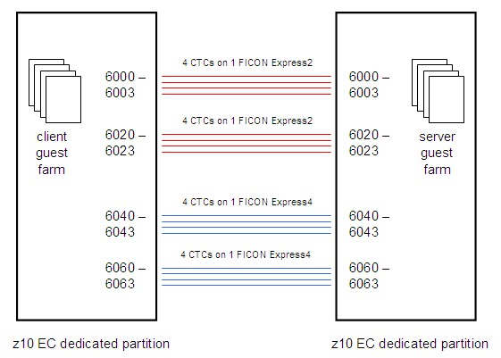
The configuration generally consists of two z10 EC partitions connected by a number of FICON chpids as illustrated in the figure below. The partitions are dedicated, one 3-way and one 12-way, each with 43 GB central and 2 GB XSTORE. Four FICON chpids connect the two partitions, four CTC devices on each chpid.
|
The CPU and memory resources configured for these partitions are far larger than are needed for these measurements. We did this on purpose. ISFC contains memory consumption throttles that trigger when storage is constrained on one or both of the two systems. In these measurements we wanted to avoid triggering those throttles, so we could see whether ISFC would fully drive the link devices when no obvious barriers prevented doing so.
The workload grows by adding guests pairwise, client CMS guests on one side and server CMS guests on the other side. Each pair of CMS guests runs one conversation between them. What specific software runs in the guests depends on whether we are exercising APPC/VM data transfers or rather are exercising ISFC Transport data transfers. More information on the software used follows below.
The logical link configuration grows by adding devices upward through the CTC device numbers exactly as illustrated in the figure. For example, for a one-CTC logical link, we would use only device number 6000, for a four-CTC logical link we would use CTCs 6000-6003, and so on.
On the client side a small CMS orchestrator machine steps through the measurements, starting and stopping client machines as needed. The server-side guest software is written so that when one experiment ends, the server guest immediately prepares to accept another experiment; thus no automation is needed to control the servers.
On each side a MONWRITE machine records CP Monitor data.
APPC/VM Workload
An assembler language CMS program called CDU is the client-side program. CDU issues APPCVM CONNECT to connect to an APPC/VM global resource whose name is specified on the CDU command line. Once the connection is complete, CDU begins a tight loop. The tight loop consists of using APPCVM SENDDATA to send a fixed-size instructional message to the server, using APPCVM RECEIVE to receive the server's reply, and then returning to the top of the loop. The fixed-size instructional message tells the server how many bytes to send back in its reply. The CDU program runs for a specified number of seconds, then it severs the conversation and exits.
An assembler language CMS program called CDR is the server-side program. CDR identifies itself as an APPC/VM global resource manager and waits for a connection. When the connection arrives, CDR accepts it and then begins a tight loop. The tight loop consists of using APPCVM RECEIVE to wait for a message from the client, decoding the message to figure out what size of reply to return, issuing APPCVM SENDDATA to send the reply, and then returning to the top of the loop to wait for another message from its client. When it detects a severed conversation, it waits for another experiment to begin.
In its simplest form this experiment consists of one instance of CDU in one CMS guest on system A exchanging data with one instance of CDR in one CMS guest on system B. To ratchet up concurrency, we increase the number of CDU guests on one side and correspondingly increase the number of CDR guests on the other side. In this way we increase the number of concurrent connections.
Other notes:
- Server reply sizes: 1, 1000, 5000, 10000, 50000, 100000, 1000000 bytes.
- Simultaneous client-server pairs: 1, 5, 10, 50, 100.
- To check regression against pre-z/VM-6.2 releases, we run an ISFC logical link consisting of only 1 CTC.
- To check APPC/VM scaling for z/VM 6.2 or later releases, we run ISFC logical links consisting of 1, 4, 8, 12, or 16 CTCs.
ISFC Transport Workload
An assembler language program called LGC is the client. This program is installed into the z/VM Control Program as a CP exit. Installing the exit creates a CP command, LGRSC. This CP command accepts as arguments a description of a data exchange experiment to be run against a partner located on another z/VM system. The experiment is to be run using CP's internal LGR data exchange API, called the ISFC Transport API. The description specifies the identity of the partner, the sizes of the messages to send, how full to keep the internal transmit queue, the size of the reply we should instruct the partner to return, and the number of seconds to run the experiment. The LGC program connects to the partner, sends the messages according to the size and queue-fill arguments specified, runs for the number of seconds specified, and then returns. Each sent message contains a timestamp expressing when it was sent and the size of the reply the partner should return. LGC expects its partner to reply to each message with a reply text of the requested size and containing both the timestamp of the provoking client-message and the timestamp of the moment the server transmitted the reply.
An assembler language program called LGS is the server. This program is installed into the z/VM Control Program as a CP exit. Installing the exit creates a CP command, LGRSS. This CP command accepts as arguments a description of how to listen for a data exchange experiment that a client will attempt to run against this server. The description contains the name of the endpoint on which LGS should listen for a client. LGS waits for its client to connect to its endpoint and then begins receiving client messages and replying to them. Each reply sent is of the size requested by the client and contains the client message's timestamp, the timestamp of when the reply was sent, and padding bytes to fill out the reply to the requested size.
The use of CP exits for this experiment is notable and warrants further explanation. Because the API used for LGR data exchange is not available to guest operating systems, there is no way to write a guest program -- a CMS program, for example -- to exercise the API directly. The only way to exercise the API is to call it from elsewhere inside the z/VM Control Program. This is why the measurement suite was written to run as a pair of CP exits. On the client side, a CMS guest uses Diagnose x'08' to issue the CP LGRSC command, thereby instructing the Control Program to run a data exchange experiment that might last for several minutes. When the experiment is over, the CP LGRSC command ends and the Diagnose x'08' returns to CMS. On the server side, a similar thing happens; a CMS guest uses Diagnose x'08' to issue the CP LGRSS command, thereby informing the Control Program to set up to handle a data exchange experiment that will be initiated by a client partner. The CP LGRSS command never returns to CMS, though; rather, when one conversation completes, the LGS program just begins waiting for another client to arrive.
In its simplest form this experiment consists of one instance of the LGC client exchanging data with one instance of the LGS server. These instances are created by a pair of CMS guests; the client-side guest issues the client-side CP LGRSC command, and the server-side guest issues the server-side CP LGRSS command. To ratchet up concurrency, we increase the number of guest pairs.
We run the LGC-LGS data exchange experiment using a variety of message size distributions:
- HS, small: Client: 20% are 512 bytes, the rest are 8192. Server always 2048.
- HM, medium: Client: 20% are 8192 bytes, the rest are 32768. Server always 4096.
- HL, large: Client: 20% are 98304 bytes, the rest are 122880. Server always 8192.
- HY, symmetric: Client: 100% are 32768. Server always 32768.
The HS, HM, and HL suites are asymmetric on purpose. This asymmetry imitates what happens during a relocation; the LGR memory movement protocol is heavily streamed with few acknowledgements.
Further, the HL workload uses a message size distribution consistent with what tends to to happen during relocations.
The HY workload, completely different from the others, is symmetric. HY is meant only to explore what might happen if we tried to run moderate traffic in both directions simultaneously.
Other notes:
- We run 1, 5, 10, 50, and 100 concurrent client-server pairs.
- We run ISFC logical links consisting of 1, 4, 8, 10, 12, 14, and 16 CTCs.